 Pressure sensor
There are many types of pressure sensors, but they are classified as shown in the table on the right based on materials.
Sensors made of semiconductor Si have a sensitivity that is about one order of magnitude higher than resistance wire sensors that use Ni and Cu alloys, and are the most widely produced.
Among them, the diffusion type, which is made by applying micromachining technology, is highly mass-producible, and the relative pressure (=gauge pressure) type can cover a wide range of about 2 kPa to 20 MPa, and the absolute pressure type can also be manufactured.
On the other hand, the film-forming type using a SUS diaphragm is suitable for high pressure applications, and the capacitance type using parallel plates is suitable for low pressure applications.
Diffusion and capacitive sensors have also been produced as integrated sensors. As for the package, mainly CAN is used for automobiles, plastic for consumer use, and SUS case for high-pressure and food products.
| Material | Method | Output element | Displacement Base material |
Package |
|---|---|---|---|---|
| Ni, Cu alloy | Resistance wire type | Strain gauge | Polyimide etc. sheet Sheet of polyimide, etc. | Nothing SUS |
| Semiconductor silicon | Diffusion type | Strain gauge | Si diaphragm | CAN Plastic SUS |
| Deposition type | Strain gauge | SUS Diaphragm | SUS | |
| Capacitive type | Al film | Si diaphragm | Plastic | |
| Ceramic | Capacitive type | Metal film | Alumina Diaphragm |
SUS |
| Others | Mechanical type | Sliding resistance Brass plate Light receiving element |
Spring | Many kinds |
Working Principle of Diffusion Pressure Sensor
Working Principle of Diffusion Pressure Sensor
As shown in the plan view of the figure 1, the pressure sensor chip has strip-shaped gauges formed at four locations in the same direction by impurity diffusion and as shown in the cross-sectional view, the diaphragm-processed Si is bonded to the glass pedestal, and become chip.
When this sensor chip is built into various cases and pressure is applied from the glass pedestal side, the A and C gauges are deformed like イin the schematic diagram and the resistance value increases, and the B and D gauges are deformed like ロ and the resistance value decreases.
Practically, it is connected to a Wheatstone bridge as shown in the wiring diagram, and the potential difference between the + and – terminals is used as the output. Contrary to the previous case, when pressure is applied from the Si side, the increase and decrease of the gauge resistance will be reversed, and the + and – of the output will also be reversed accordingly.
Some chips are wired full bridge on the Si surface, while others are easy to adjust the offset voltage externally by opening the No. 1 and No. 6 terminals as shown in this figure.

Structure of the pressure sensor
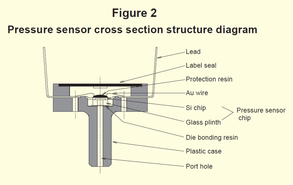
The figure 2 shows the cross-sectional structure of a case-type semiconductor pressure sensor for gauge pressure.

Various characteristics of pressure sensors
Pressure sensors are required to have many characteristics as shown below.
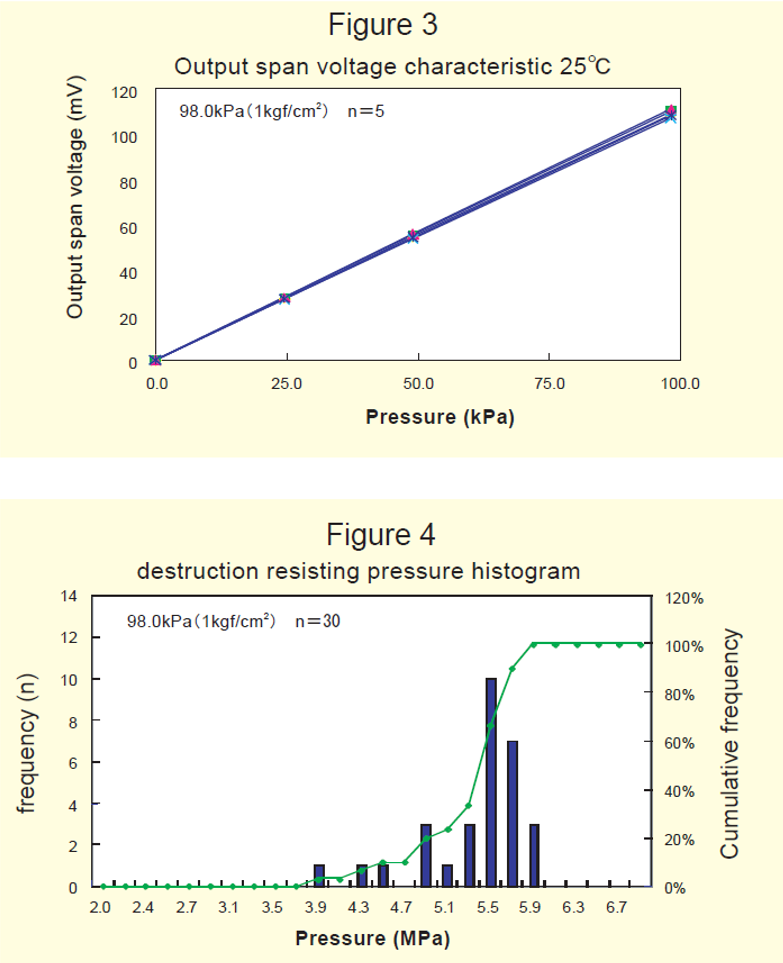
The main characteristics are the output span voltage (Fig. 3) and breakdown voltage histogram (Fig. 4) of our product.
