 AMR Sensor
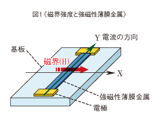
The AMR sensor consists of the Si or glass board, and the thin film of alloy formed on the board. The principal ingredient of alloy is ferromagnetic metals, such as Ni and Fe. By patterning it, the direction of the magnetic walls (boundary of magnetic domain and wall) is equal to length direction and indicates the shape anisotropy. When applying the current to the ferromagnetic thin film metal, and applying the magnetic field H to the direction X (as shown in the figure 1), which is vertical to the current direction Y, the resistance decreases according to the strength of the magnetic field.

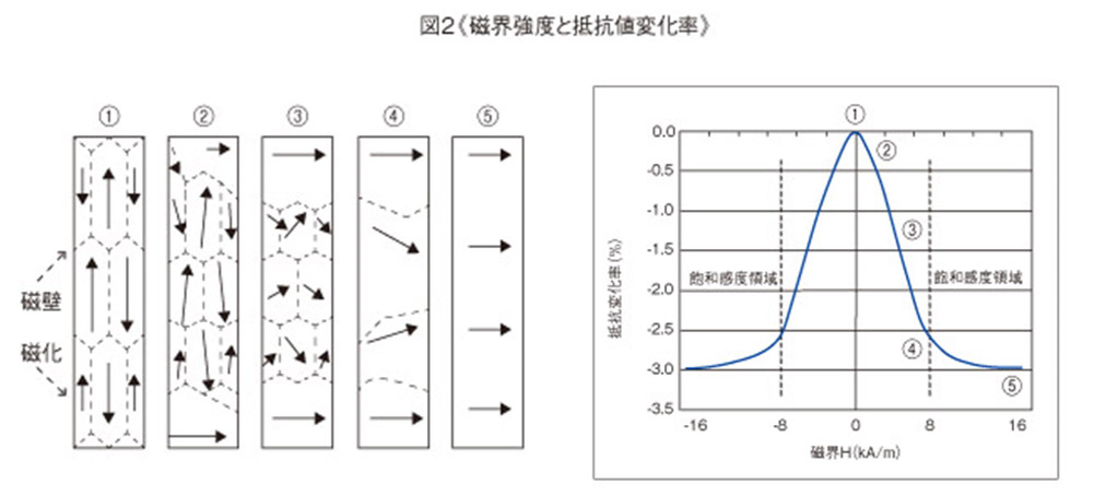
An image of the change based on the connection that resistance value and magnetic wall/magnetization change is shown in the figure 2.
In a state where there is no external magnetic field as shown in ①, magnetizations cancel each other and external magnetic field isn’t generated.
As shown in ②, while the external magnetic field is weak, the magnetic walls move and the volume of the magnetic domain that matches the direction of the external magnetic field increase.
As shown in ③, as the external magnetic field becomes stronger, magnetizations rotate within the magnetic domains.
As shown in ④, as the direction of magnetization moves toward the direction of the external magnetic field, the magnetic walls decrease.
In ⑤, the whole becomes one magnetic domain state (single magnetic domain state) and becomes saturated.
An AMR sensor when an external magnetic field is applied in a direction perpendicular to the length direction of the pattern, the resistance value decreases according to the magnetic field strength. AMR sensors utilize this effect.

As shown in the figure 2, the resistance change rate varies up to about 3% according to the field strength. The outside area of the region where the resistance change amount (ΔR) can be approximately shown by the expression (1) is called the saturated sensitivity region.
In the region, after the filed strength exceeds the specific value, the resistance value does not change.
∆R∝H^2…(1)
In addition, because of f(H) = f(-H), the direction of N pole to S pole cannot be distinguished with the direction S pole to N pole.
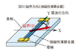
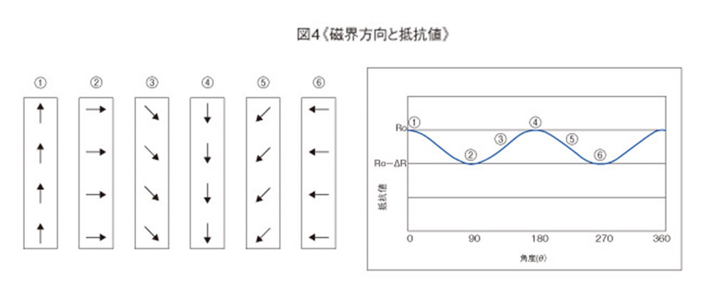
Next, it is noted about the case as shown in the figure 3 that the current is applied to the ferromagnetic thin film metal, the magnetic filed is applied with the strength where the resistance change amount will be saturated, and the filed direction will be rotated (the angle θ) with the current direction Y. The image of resistance and magnetization changes are shown in the figure4. When external magnetic field rotates in the saturated sensitivity region, the direction of the magnetization rotates in the same direction as external magnetic field.


the resistance change amount (ΔR) becomes maximum when the current direction is vertical with the filed direction (θ=90°②, 270°⑥), and becomes minimum when the current direction is horizontal with the filed direction (θ=0°①, 180°④). The resistance value of the AMR sensor can express as the function of the angle (θ) that formed by the direction of the current and magnetic field.
R=R0-∆Rsin2 θ…(2)
Ro : the resistance value of the ferromagnetic thin film metal in the non-magnetic field
ΔR : resistance change amount
θ : the angle which indicates the magnetic field direction
In the saturated sensitivity region, ΔR becomes constant,and does not vary according to the filed strength.
As explained earlier, one is a type utilizing the principle to detect the strength of the field with the constant direction, and the other is a type utilizing the principle to detect the filed direction in the filed whose strength exceeds the saturated sensitivity region. The form of the ferromagnetic thin film metal is different between two types. The former is called 【parallel sensingline type】, and the latter is called 【vertical type】. We support the two types of the detection method.