浜松光電

Magnetic SensorsAMR Sensor

Technical data:vertical type AMR sensor working principle

The figure 17 shows the form of ferromagnetic thin film metals on the AMR sensor utilizing the principle to detect the field direction in the filed whose strength exceeds the saturated sensitivity region. This AMR sensor has two ferromagnetic thin film metal elements, which are R1 arranged perpendicularly and R2 arranged horizontally. They are connected in series. We call this type 【vertical type MR sensor】.

The change of resistance caused by applying the magnetic field to the horizontal direction (X) is the largest for the element (R1), and the smallest for the element (R2). As shown in the figure 17, If the magnetic field that strength,which reaches saturated sensitivity region applies, and the angle changeθ, which is applied against the direction of the magnetic field Y, the resistances of R1 and R2 are shown by the following expressions.

R1=R0-∆Rsin2 θ…(4)
R2=R0-∆Rcos2 θ…(5)

When arranging the elements as shown in the figure 19, they form the known Wheatstone bridge.

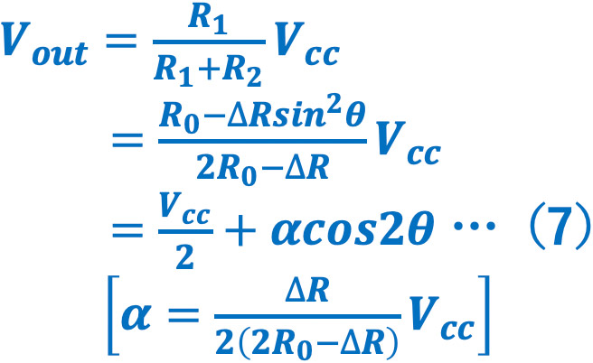
Following explains the change of the field direction caused by the magnet motion (figure 20: rotary motion, figure 21: linear motion), and the AMR sensor output. In both of the figures 20 and 21, an AMR sensor is arranged so that the change of the field direction can have an influence on the sensor, with a gap (distance between the magnet and the AMR sensor) where the field strength exceeding the saturated sensitivity region will be applied to the sensor. In the figure 20, when the magnet is rotated one time, the filed direction rotates one time on the sensor. Accordingly, the output wave becomes two cycles from the expression (7) Vout=Vcc/2+αcos2θ. In the figure 21, when the magnet moves for the distance λ, the filed direction rotates a half on the sensor.

In addition, as for information of the motion direction, it can be obtained either by arranging two AMR sensors at the location of a-and-b or a-and-d shown in the figure 21, or by putting two sensors together and rotating one by 45°as shown in the figure 22. These arrangement has an advantage to obtain two output signals phase shifted by 1/4 cycle(90°) at any pole-magnetization pitch λ.

However, as for the arrangement of two sensors, there are two issues, the mechanical positioning and the characteristic difference between sensors. The figure 23 shows the AMR sensor to solve these issues. The method is to put two full bridge elements together, rotate one by 45°, and arrange them on one board. That will be able to solve the issues, and make precise sine waves and cosine waves with only one AMR sensor.

In addition, a bias filed is also applied to the direction rotated by 45°against to the sensing elements on a sensor as shown in the figure 24.This will reduce the cycle by half, and enable to distinguish N pole with S pole, as same as the Hall element. Moreover, it is the best to make the filed strength of the bias magnet same as the strength which shifts into the saturated sensitivity region.

Support
Reference materials

keyword

Search for sensors by related keywords

  • #what Pressure sensorA pressure sensor in the medium pressure range that uses the semiconductor piezo effect. The lineup includes abundant pressure range and SMD type of small package They are characterized by high breakdown voltage compared to other companies. What is the pressure sensor?
  • #what AMR sensorA sensor that uses the magnetoresistive effect of a ferromagnetic material to change the resistance value according to the strength of the magnetic field. It has sensitivity in low magnetic fields, a wide operating temperature range, and excellent frequency characteristics. You can use it in harsh environments where optical systems cannot. What is the AMR sensor?
  • #magnetic sensorA sensor that uses the magnetoresistive effect of a ferromagnetic material to change the resistance value according to the strength of the magnetic field. It has sensitivity in low magnetic fields, a wide operating temperature range, and excellent frequency characteristics. You can use it in harsh environments where optical systems cannot. Magnetic sensor
  • #magnetic switchOur AMR sensor can use for magnetic switch (proximity switch). We will introduce how it works and how to use it. Sensor for magnetic switch Application examples
  • #water heatersOur water level sensor is installed on water heaters, can detect water level and water pressure of tap water, hot water. Equipped with a semiconductor pressure sensor, it has excellent linearity and reproducibility. Sensor for water heaters.
  • #water level sensorsDeveloped for detecting the water level of water heaters, this sensor can detect water level and water pressure of tap water, hot water, etc. Equipped with a semiconductor pressure sensor, it has excellent linearity and reproducibility. Water lever sensor
  • #water meterBy intermittently driving the sensor, it can be used for low current consumption applications such as battery-mounted flowmeters. Water mater
  • #potentiometerOne of the application of the AMR sensor that can detect 360°is Potentiometer. We will introduce how to use and how to detect as potentiometer. Sensor for potentiometer
  • #encoderOur AMR sensor can use for various encoders. Sensor for rotary encoder Sensor for linear encoder Application examples
  • #chip mounterWe will introduce the examples of our pressure sensor. Sensor for chip mounter Application examples
  • #blood pressure monitorOur pressure sensor is used for medical equipment required low noise. Sensor for blood pressure gauges Application examples
  • #360°detectionWe have a lineup of the AMR sensor that can detect 360°detection by mounting bias magnet. AMR sensor for 360°detection Application examples
  • #gear detectionWe have a lineup of gear sensors using TMR sensors.
  • #how to use AMR sensorWe will introduce one of the examples of how to use magnetic sensor. (Application examples)
  • #how to use Pressure sensorWe will introduce one of the examples of how to use pressure sensor. (Application examples)