 AMR Sensor
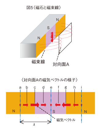
Following explains how the magnetic field strength changes according to the motion of magnets. As shown in the figure 5, lines of magnetic force go out from the N pole center to the S pole center on magnets. When expressing the field strength with magnetic vectors, the magnetic vectors with the same direction as the lines of magnetic force occur on the surface A, which is opposite to the magnet. The vector strength is minimum at each center of N pole and S pole (a, e, i), and maximum at the boundary of N pole and S pole (c, g). At each middle of a-e-i and c-g (b, d, f, h), the field strength is half of that at c-g.
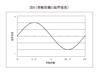
When a multi-pole magnet moves for 2λ at constant speed, the filed strength change at the position “a” will be expressed by the signal in the figure 6, and the wave form will be the sine-wave.
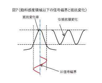
This field strength change will cause the resistance change on a ferromagnetic thin film metal. When the filed strength is under the saturated sensitivity region, the resistance will change as shown in figure 7. In the figure 7, the wave H expresses the signal field, and the resistance change caused by the wave H is the wave G. When the signal filed moves for one cycle, the resistance change generates a two cycle wave form.
The figure 7 shows the case in which the signal field strength is under the saturated sensitivity region. On the other hand, the figure 8 shows the case in which the signal field strength is over the saturated sensitivity region.
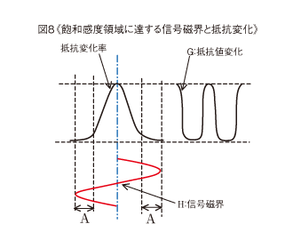
In the range A, the strength is over the saturated sensitivity region, and the resistance change rate becomes extremely small. Accordingly, the resistance change G will generate different wave form from the figure 7. When measuring the resistance change by the voltage change on a half bridge circuit, the Vout will be shown by the following expression.

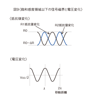
The figure 9 shows the resistance change for the parallel sensingline type basic pattern, shown in the figure 11, and the output voltage at the time of applying the signal field under the saturated sensitivity region, shown in the figure 7. The output will becomes sine-wave signals.
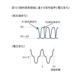
The figure 10 shows the output at the time of applying the signal field over the saturated sensitivity region, shown in the figure 8.
When the field strength is over the saturated sensitivity region, the wave form for the voltage change will be also distorted.This distortion component can express as the higher harmonic wave.
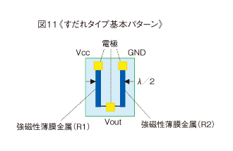
The figure 11 shows the parallel sensingline type basic pattern. Expressing with the pole- magnetization pitchλ explained in the figure 5, the arrangement as that R2 becomes minimum when R1 is maximum is the position that they are just λ/2 apart. By forming two elements of ferromagnetic thin film metals with the same direction at this position, connect them in series, form a half-bridge circuit, the signals can be taken out efficiently.
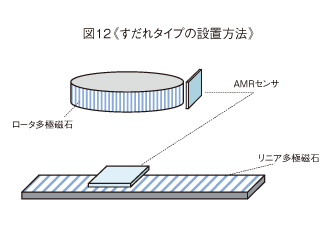
As shown in the figure 12, arrange this 【parallel sensingline type AMR sensor】 As it becomes opposite to the detect object which is the multi-pole-magnetized rotor or the magnetized face of the linear multi-pole magnet.
It is necessary to note the distance (gap) between the magnet and the sensor. The figure 13 shows the relationship between the gap and the output voltage. When requiring a precise wave form as shown in the figure 9, it is necessary to set the gap between the magnet and the AMR sensor within a specified range. When arranging them with the gap A shown in the figure 13, since the filed strength will be in the saturated sensitivity region, the wave form distortion like the figure 10’s will be generated. As for the gap B shown in the figure 13, the output voltage will change on a large scale with a slight difference of the distance. This is because of that the filed strength decreases in proportion to the square of the distance.
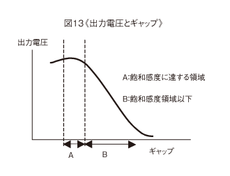
So,in the basic pattern of a parallel sensingline type, it can used efficiently within the limits of the gap regionB. Our AMR sensor has been added to the basic pattern to reduce waveform distortion in the gap region A shown in the figure 13, as well as in the gap region B.
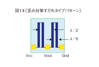
By comparison with a triangle wave and a sine-wave, if you add the pattern that is smaller than sine-wave signals and reinforce the sensitivity, the output of the triangle wave will approach that of the sine-wave signals. By placing the pattern at λ/6 for the third harmonic wave,λ/10 for the fifth harmonic wave, distortion is corrected and a highly accurate output signals can be obtained even a wide gap. Third harmonic wave measures pattern is shown in the figure 14.
In addition, it is possible to use various techniques such as differential output patterns and patterns that suppress curvature errors.
When controlling the motion, it is necessary to know the motion direction.
Although it is difficult with one signal, but it is possible to using two signal. It can be effective means to combine one output with another phase shifted by 1/4 cycle (90°) from the basic output.
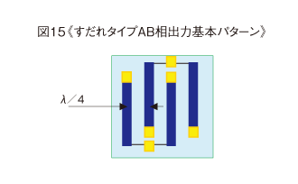
These outputs can be obtained by arranging two pairs of AMR sensors, which are in the form of the basic pattern in the figure 11 and λ/4 apart. This arrangement enables two output signals phase shifted by 1/4 cycle, necessary for the motion control. This phase output type is shown in the figure 15. Since two pairs of the patterns are formed on the same board,
There is an advantage that can reduce errors for position and characteristics.
As described in the above, it is the primary characteristic of this AMR sensor to be able to form the sensing elements on the same board without restraint. Utilizing this characteristic more will also enable the absolute function.
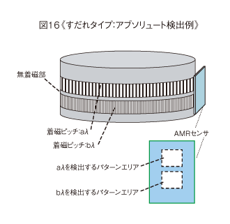
The sample is shown in the figure 16. The detected object is a multi-pole magnet, which has two different pole-magnetization pitches λa andλb. The absolute detection will be enabled by detecting these two different magnetic poles with one AMR sensor and processing the output signals. An area not magnetized is required on the boundary of the pole-magnetization pitches λa andλb (non-magnetized area). The width of this area should be 0.5mm when λ is shorter than 0.5mm, and equal toλ when λ is longer than 0.5mm.
